Integrating soil moisture sensor technology into seeding equipment to optimise seeding depth and crop establishment
Integrating soil moisture sensor technology into seeding equipment to optimise seeding depth and crop establishment
Author: David Finlay (MPT), Gordon Howard (MPT) | Date: 15 Feb 2024
Take home message
- A common objective in seeding is to have all seeds placed into a uniform soil moisture profile to achieve a uniform emergence. This may involve scenarios involving both moisture seeking as well as dry sowing
- Traditional seeding equipment is generally focused on providing a seeding outcome where a consistent depth outcome is achieved
- Whilst acknowledging that uniform depth is a desirable outcome, it does not necessarily result in a uniform emergence outcome if there is soil moisture profile variability across a field
- The aim of this project is a semi-autonomous seeder that uses in-furrow soil sensors to determine the status of soil moisture, such that hydro-electric row units can be adjusted in real-time within field.
Introduction
Over the course of many years, manufacturers of seeding and tillage equipment have consistently endeavoured to introduce innovative solutions designed to address specific challenges encountered during the seeding process. These solutions encompass a range of features, including consistent depth, breakout, trash flow, and press wheel functions, among others. While these features are undeniably important, a limitation lies in their ability to deal and react to variabilities within the soil.
The evolving landscape of agricultural technology has witnessed significant progress in both proximal and remote sensing. These advancements hold the potential to offer valuable insights into areas where variability is occurring within soils, however they often require ground truthing to validate their findings or may overlook regions with alternate soil properties.
An alternate approach to address these challenges involves the integration of sensors directly into the in-furrow arrangement of the seeder. This strategic placement allows for the real-time mapping of soil properties as the seeder traverses a field. The utilisation of this data during the seeding process allows the potential for optimising seed placement in-field by enabling adjustments to various mechanical aspects of the seeder mechanism.
Non-uniform crop emergence
The occurrence of uneven crop emergence is often attributed to variability in soil moisture levels within the seed zone during or shortly after planting. The moisture present at seed depth might be sufficient for germination and emergence in certain sections of a field but insufficient in others.
When planting seed into dry soil, seeds may not germinate and emerge until a rainfall event occurs, which could be weeks after the initial planting. Consequently, a field may exhibit a mix of more and less established crop, with the discrepancy aligned with the duration from planting to the onset of rainfall.
Uneven emergence often leads to non-uniform maturity within a crop. The earliest emerging plants may reach maturity sooner than later-emerging plants This non-uniformity can complicate harvest timing and reduce overall yield.
Areas with delayed crop emergence may provide opportunities for weed growth before the crop canopy is established. Weeds can compete with crops for essential resources, further increasing the negative impact on crop yield.
In-furrow soil sensing
During the 2010’s deep seeding crops became common, partially due to seasonal conditions, and partially due to the increased production of chickpea, which can handle emerging from greater depths than many crops.
Whilst ‘moisture seeking’ was a proven method to improve crop establishment in marginal soil moisture conditions, it resulted in significantly higher fuel use, and was often related to structural fatigue of seeding equipment.
By embedding soil moisture sensors into an autonomous row unit with automatic depth control, a more optimised seed placement could potentially be achieved across an entire field, thus improving plant establishment, whilst potentially reducing fuel use in areas where soil moisture profiles were more favourable.
Technology trials
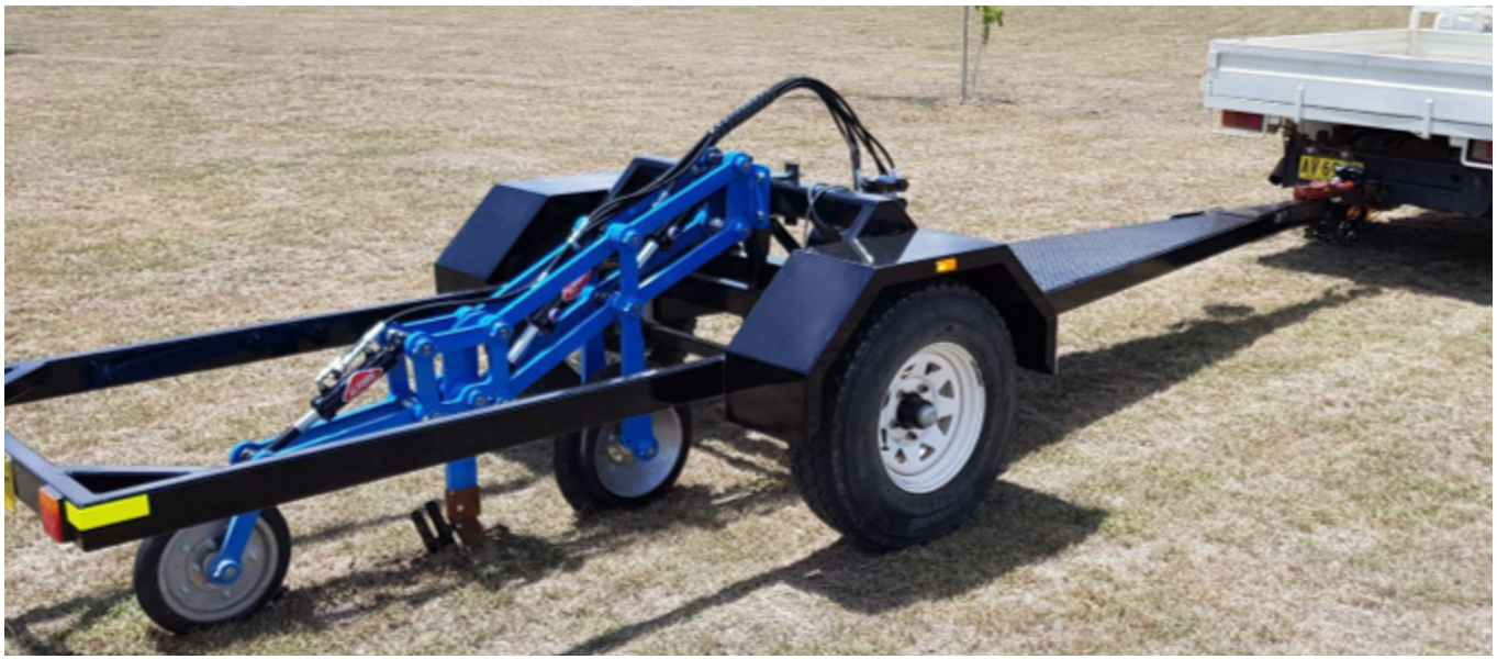
In the preliminary phases of implementing this technology, trials were initiated using a single-row unit mounted on a trailer (Figure 1). This experimental setup served as a platform for testing various sensor types and gaining insights into the operational requirements of the hydraulic control, software, and mechanical requirements for the effective functioning of the row unit.
The utilisation of a single-row unit provided a valuable testing ground for different sensor types. It facilitated a hands-on exploration of the hydraulic control system, allowing for a comprehensive understanding of its intricacies in ensuring the optimal performance of the row unit. This initial testing phase played a pivotal role in refining the technology and establishing a foundation for further advancements.
Figure 1. First single row trial unit.
Despite the informative nature of these trials, a limitation arose due to the generation of only a single data set from the soil sensor. This singular dataset presented challenges in comprehensively assessing the performance of the specific sensor type, especially in comparison to alternative sensor types. The absence of multiple datasets limited the ability to conduct robust comparative analyses, impeding a refined evaluation of each sensor's advantages.
In essence, the single-row unit trials, while instrumental in determining the functionality of the hydraulic control system and testing different sensor types, highlighted the need for a more comprehensive approach to data collection.
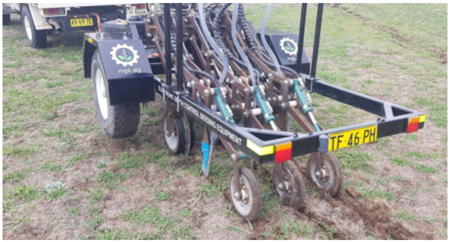
To overcome the limited testing capacity of the single row machine, a 3-row unit was constructed (Figure 2). The transition from a single row unit to three introduced a more complex requirement to the hydraulic control system and the control software. This sophistication was essential to ensure the seamless coordination and functionality of multiple row units simultaneously. The expanded setup not only allowed for a comprehensive evaluation of the hydraulic control software's adaptability but also enabled a concurrent assessment of different sensor types.
However, beyond a seeding depth of approximately 100 mm, ground slippage became significant, particularly as a conventional road-going vehicle was used as the driving source. This limitation posed a hurdle to achieving full optimal performance.
The incorporation of three row units outlined the interplay between hardware and software components. The hydraulic control system needed to navigate the complexities of managing multiple row units, ensuring uniformity in seeding operations while accommodating the nuances introduced by different sensor types. This phase of development served as a baseline for refining not only the mechanical aspects but also the software algorithms that controlled the system's responsiveness.
Despite the challenge posed by ground slippage, the utilisation of three row units presented a unique opportunity for comprehensive testing and refinement. The concurrent evaluation of different sensor types allowed for a better understanding of each sensor's strengths and weaknesses under field conditions. This process contributed to the improvement of the technology, bringing it closer to achieving the desired outcome of the product.
Figure 2. Second trial unit with 3 rows.
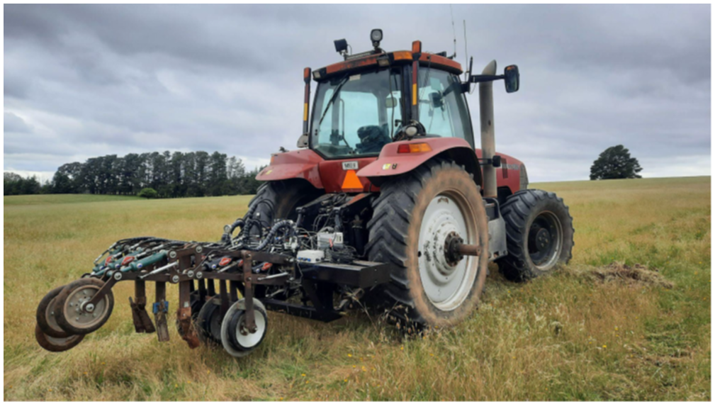
After the initial trailer arrangement, the machine was rebuilt onto a linkage frame (Figure 3). This adaptation not only allowed for better trials but also extended the operational capacity of the machine, enabling it to reach a maximum working depth of 250 mm.
The mounting on a tractor allowed integration in the tractors hydraulic system. This integration not only streamlined the overall hydraulic functionality but also offered the advantage of freely adjustable flow rates. Moreover, the seamless connection to the tractor's hydraulic system ensured a readily available fluid source, eliminating the need for electronic on/off fluid control. This on-tap fluid availability increased the machine's efficiency, allowing for dynamic adjustments and responsive control during various phases of operation.
Within this refined setup, a comprehensive network of pressure and load sensors was strategically incorporated. These sensors were positioned to cover the entire row unit, capturing data across various seeding depths. This arrangement allowed for the measurement of force settings throughout the entirety of the row unit, offering a detailed understanding of the forces experienced at different depths during the seeding process.
The integration of pressure and load sensors enabled the quantification and analysis of forces exerted by the row unit at different seeding depths. This data set not only provided valuable insights into the machine's performance but also facilitated the fine-tuning of force settings to achieve optimal outcomes across different soil conditions.
Figure 3. Third trial unit with 3 rows on a linkage toolbar.
During product development we had made substantial progress in defining the mechanical, hydraulic, control software, and sensor components. However, a critical phase remained – validating the system's functionality at scale. The existing 3-row machine, while informative in early trials, had limitations in its hectare-per-hour rate and faced challenges in discerning significant changes in soil properties over small areas.
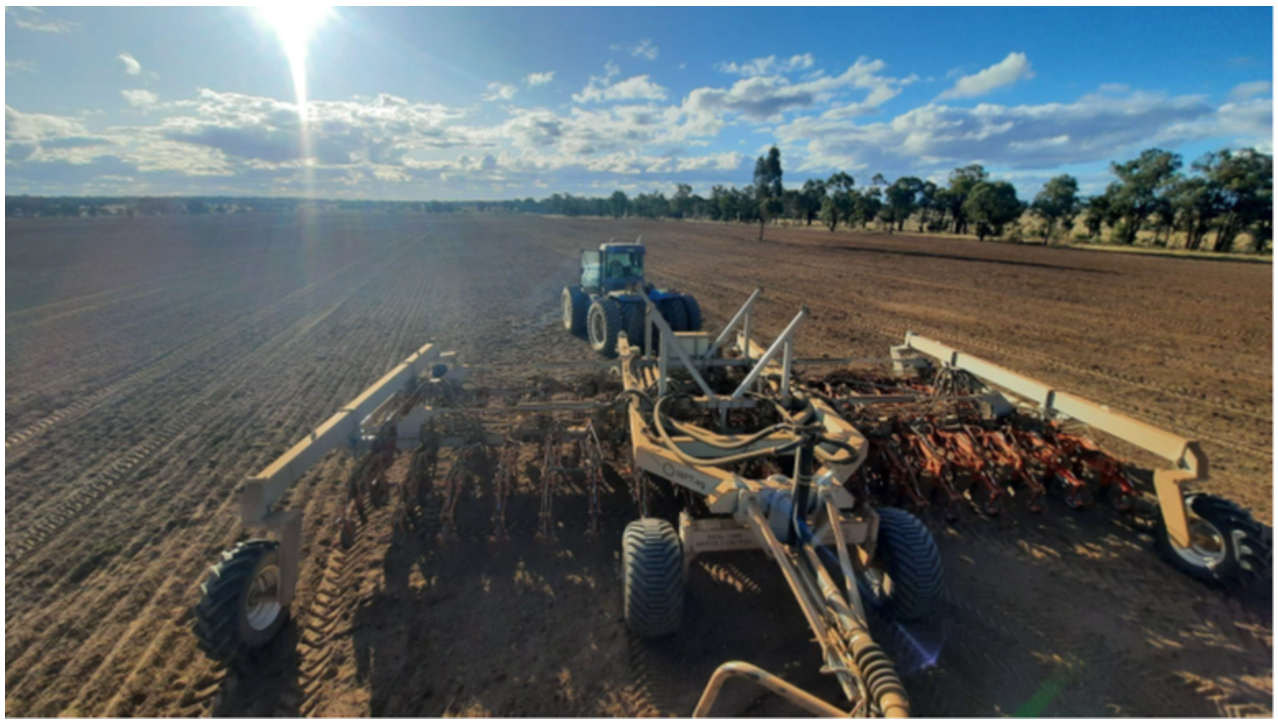
To address these limitations, a strategic decision was made to acquire an existing 12-meter seeder frame. This larger frame offered the potential to scale operations and rapidly evaluate the technology over more extensive areas. The frame was retrofitted with 36 row units spaced at 333 mm intervals (Figure 4).
A trial site was selected in Tullamore, central New South Wales, providing a diverse and representative location for testing. The 120-hectare site offering a suitable area to assess the system's performance under more realistic conditions.
Whilst the large-scale trials proved successful, it involved significant works in commissioning the machine, primarily involving changes to the operational software in modifying the routine on how the rows engage and disengage as required during the course of performing the seeding tasks. On top of this, was the various ancillary requirements of engaging the seed cart, and in-field guidance.
Figure 4. 12-metre-wide frame, with 36 rows fitted during the 2023 winter cropping trials.
What’s next?
With an operational full-scale seeder in place, the validation and ROI works are the key priority.
During 2024, the key project objectives include:
- ISOBUS integration
The seeder is currently operating under its own control suite, however upgrading to an ISOBUS control will not only simplify operation of the seeder but will potentially allow for an integrated semi-autonomous operation of the seeder with minimal user input. This development is aimed at allowing for both the current deskilling of the agricultural workforce and the future automation of both tractors and implements. - New sensor development
Currently working with a Sydney based university to improve the sensor array. This research is intended at improving both sensor accuracy and sensor wear resistance. - Crop trials
Increased cropping trials in a variety of zones, running in conjunction with standard seeding equipment to determine performance of the technology when compared to conventional seeders. These trials will allow the continued development and optimisation of the sensor technology, the automatic control of the seeder functions, and the simplification and refinement of the seeder user interface.
Acknowledgements
The research undertaken as part of this project is made possible by the significant contributions of growers through both trial cooperation and the support of the GRDC, the author would like to thank them for their continued support.
The research undertaken as part of this project is also made possible by significant contributions from the Department of the NSW Chief Scientist & Engineer, and the author would like to thank them for their continued support.
The author would also like to acknowledge the continued startup support from Cicada Innovations, and Sparklabs Cultiv8.
Contact details
David Finlay
mpt.ag
74 Astill Drive, Orange NSW 2800
Ph: 0417 920 803
Email: david@moistureplant.com
Date published
February 2024
GRDC Project Code: SEN2312-001RTX,


